| Modeling/ Lattice Mapping |
Lattice MappingThe lattice mapping system allows you to attach an object to another object called lattice. When the lattice object is modified, also the attached object becomes modified accordingly. Any object can act as a lattice object. For example, you can attach a number of logos to a NURBS curve and deform the curve to control the positions of the logo objects. The idea is that a complex geometric object, such as body of a character, can be controlled easily using a simpler object, such as a skeleton.
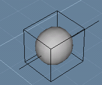
Map a sphere to a curve1. Create a SDS sphere. 2. Create a horizontal straight NURBS curve consisting of four control points and passing through the sphere.
3. Multi select both objects, the SDS sphere first, the curve second. Make sure that you select the objects in this order because the 'Mapping tool' maps the first selected object to the last selected object. 4. Click the Map tool in the 'Lattice Mapping' tab of the toolbar. You can now see a couple of mapping specific options in the control bar. These default options are just fine, so accept the tool.
We have now mapped the sphere to the curve. Select the curve and move it. The sphere is moved with the curve. If you rotate the curve, also the sphere gets rotated. 1. Select the SDS sphere 2. Open the property window and go to the 'Map' tab. 3. Reset the 'Rotate' check box.
If you now rotate the NURBS curve, the sphere is only moved. In other words, the curve controls only the position of the sphere. If you want to use the curve to control the orientation of the sphere, not the position, just reset the 'Translate' check box and set the 'Rotate' check box. Pointwise mappingIn the previous example, we mapped a sphere to a curve using 'object' mapping option. Therefore, the lattice curve controlled the four properties of the 'object space' of the sphere: position, size, orientation and skew. To allow lattices to fully deform objects, point mapping should be used instead of object mapping. To map an object to a curve using 'pointwise' mapping: 1. Create a freeform object (such as a SDS cylinder, which contains enough points to allow interesting deformations). Create also a NURBS curve passing through the mesh just like we did in the previous example.
2. Select both the cylinder and the curve in that order. Click the Map tool. Now you can again see the mapping options in the Control Bar. Set the 'Mapping mode' field to 'Pointwise' and accept the tool.
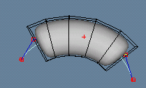
3. Now select the curve and enter 'Edit' mode. Point edit the NURBS curve. The mapped mesh is deformed with the curve.
Modifying mapped objectsIf the position of the mapped object is not correct, you can simply move it into the new position. For example: 1. Select the SDS cylinder we created in the previous example and turn off the 'Edit' mode if it is still on. 2. Activate the Move tool. 3. Click a point on the lattice curve. When you move the mouse, you can see how the SDS cylinder moves along the curve. When a desired position is found, click the mouse again.
Note: when moving mapped objects, the first point entered for the Move tool is very critical. Make sure you click over the curve so that the move tool has a good reference point to start moving the target along the curve. If the first point for the move tool is heavily displaced from the curve, the moving route in the curved 'lattice space' is not intuitive, making the operation hard to control. Detaching mapped objects from latticesYou can unmap an object from a lattice object by using the Unmap tool. For example, to detach the SDS cylinder from the curve. 1. Select the SDS cylinder and the curve objects (in this order). 2. Activate the Unmap tool and click the 'Accept' button in the tool control bar.
If you now modify the curve, the SDS cylinder is not affected in any way. Mapping multiple objects to a latticeYou can map any number of objects to a single lattice object. There are two ways to accomplish this. First, you can multi select all the objects and map them to the desired lattice object at once. Just make sure the lattice object is the last selected object when accepting the Map tool. Or, you can select and map objects to a lattice object one by one. You can repeat the Map tool any number of times for the same lattice object. Let's map a number of spheres to a curve. 1. Create five small analytic spheres and a NURBS curve passing through the spheres.
2. Multi select all objects by clicking their names on the select window one by one: spheres first and the curve last.
3. Activate and accept the Map tool with the default options. Modify the NURBS curve. The spheres are modified with it. Path animationsAn object moving along a path is simply an object moving in lattice space. For example, when a sphere moves along a NURBS curve, its 'lattice coordinate x' is animated. You can animate mapped objects just like you can animate regular unmapped objects using the keyframer, Let's animate a sphere moving along a path by key framing the motion manually: 1. Create a sphere and a NURBS curve representing the desired motion path 2. Select the sphere and the curve (in that order) and apply the Map tool in 'Object' mode. The sphere is now mapped to the NURBS curve. Move the NURBS curve and the sphere moves with it. If you move the sphere, it travels along the curve. 3. Open the animation window and activate animation recording from the red button at the right end of the animation window. Make sure that the time slider is set to frame 0 and move the sphere to the beginning of the curve. This creates the first key frame for the sphere. 4. Move the time slider to the last frame. Move the sphere with the move tool along the curve to a new position. A second key frame becomes created. 5. Turn off animation recording and play with the time slider to see how the sphere moves between the two positions. This is exactly what the actual 'Animation/Path' tool does: it maps selected objects to the given path and creates two key frames, which move the mapped objects along the curve. It performs the above mentioned steps in one easy to use operation.
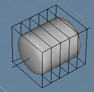
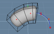
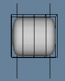
Swapping lattice objectsThe Reconnect tool detaches objects from their current lattices and attaches them to a new lattice object. For example, a sphere moving along a NURBS curve can be reconnected to a skeleton to get the sphere to move along the skeleton. Note that only the lattice object is switched. All other mapping information remains untouched. This tool can be very useful when you need to map complex objects to curved lattices. For example, you might want to map a NURBS mesh to move along a cylinder surface. Instead of trying to bend the mesh to match the shape of the cylinder, simply map the mesh to a planar surface and animate it there. When the animation is ready, reconnect the animated mesh to its actual cylinder lattice. Let's see how this works. 1. Create a NURBS mesh (rectangle) consisting of 5 x 5 points and map it to a bigger analytic rectangle using pointwise mapping. 2. Activate animation recording and move the mesh in the initial position in the beginning of the animation. 3. Move the time slider to the last frame and move the mesh to another position. You can also single point edit the mesh for animated deformations. 4. Reset animation recording and play the animation to see how the NURBS mesh moves in the space defined by the analytic rectangle. 5. Now, create an analytic cylinder (actually a NURBS cylinder or sphere or any other geometric object with a curved surface will do). 6. Select the animated NURBS mesh and the new cylinder, activate the Lattice Mapping/Reconnect tool and click 'Accept'. Play the animation to see how the mesh moves along the surface of the cylinder. Multi mappingThe previous examples used only one lattice object. However, a single object can be mapped to any number of lattice objects. For example, you can use multiple NURBS curves to control different parts of a single SDS mesh. Let's see how this work. Let's create a SDS cylinder whose left side is mapped to one curve and the right side is mapped to another curve. 1. Create a horizontal SDS cylinder (use for example 4*8 points) and two vertical NURBS curves at both ends of the SDS cylinder.
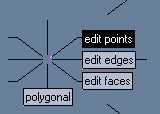
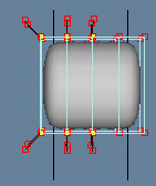
2. Select the SDS cylinder and enter point editing mode (select 'Edit Points' from the compass). 3. Select all the left side points of the SDS cylinder using dragging.
4. Multi select the SDS cylinder (with its left end points selected) and the left side NURBS curve in this order. If you look at the View window now, you can't see any points selected in the SDS cylinder. This is normal. The points are still selected, although not highlighted because of multi-selection situation. 5. Activate the Map tool and set the 'Mapping mode' option to 'Selected points'. Then accept the tool.
Try moving the left side NURBS curve now. The left end of the SDS cylinder is moved with the curve. 6. Now repeat the steps 3...5 for the right side points of the SDS cylinder. In other words, select the right side points of the SDS cylinder, then multi select the right side NURBS curve and apply the Map tool again with the 'Selected points' option. Weighted mappingThe 'Weight' parameter controls how strongly lattice objects affect the mapped points or objects. This is often needed in multi mapping. For example, you can map a point on two lattices so that the first lattice affects the point with 30% strength and the other one affects the point with 70% strength. Or you can define weights so that the shorter the distance to a skeleton, the stronger the skeleton affects the points/objects.
Let's multi map a SDS sphere to two NURBS curves and experiment with weights: 1. Create a SDS sphere and two identical NURBS curves passing through the sphere (duplicate the curve to get two identical curves). 2. Select the sphere and the first curve just like we did in the previous examples and apply the Map tool using 'Object' mapping mode. 3. Map the sphere on the second curve. You have now mapped the sphere on two curves using equal full weights. 4. Now move the curves. The sphere is always located exactly between the NURBS curves, because both curves affect the sphere with an equal weight.
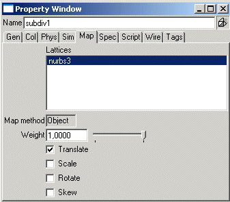
To make the first curve affect the sphere only 10%: 5. Select the sphere, open the property window and go to the 'Map' tab. 6. The 'Lattice' field shows you the name of the first curve. Set 'Weight' to 0.1. The sphere is moved towards the second curve. 7. Now, pick the name of the second curve from the property window's lattices list. Then set also the weight of the second lattice curve to 0.1. The sphere is moved back to the center of the curves because both curves affect again the mapped object with equal (0.1) weights! Weights are like 'strings', which attempt to pull the mapped points to the position defined by the lattice objects. The higher the weight, the stronger the 'string'. Therefore, if you have only one lattice object, weights are irrelevant, because even the weakest string will pull the mapped object or point. There is no other 'string' resisting it. Using the property window to edit mapping parameters
The 'Map' tab in the Property window controls mapping parameters. Lattice mapping properties
Using the vertex painting tool to control weightsYou can use the Vertex Painting tool (this multi-purpose tool is located in the 'Materials' tab) to control weights of pointwise lattice mapping. Select the mapped object and then activate the tool. The tool control bar shows a selector 'Property to be painted'. Pick' 'Weight' from it, select a suitable brush size, define the weight and paint over the desired points.
|
 |
 |
